On this page:
See more:
- Badania układów katalitycznego oczyszczania spalin
- Badania olejów silnikowych, paliw płynnych i gazowych, dodatków do paliw
- Badania emisji spalin i zużycia paliwa
- Badania w zakresie homologacji


On this page:
See more:
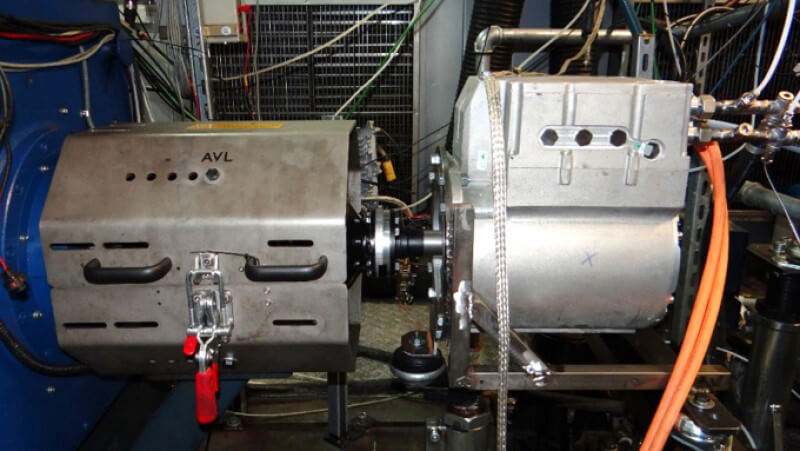
BOSMAL’s engine dyno testing laboratory, equipped with 20 modern engine dynos (AVL, HORIBA) – including dynamic dynos, hybrid testing benches and eddy current brakes – allows research and development works at the highest global level to be carried out.
BOSMAL’s engine dyno testing laboratory specialises in:
Exhaust aftertreatment system tests:
BOSMAL’s engine dyno testing laboratory tests the following engine types:
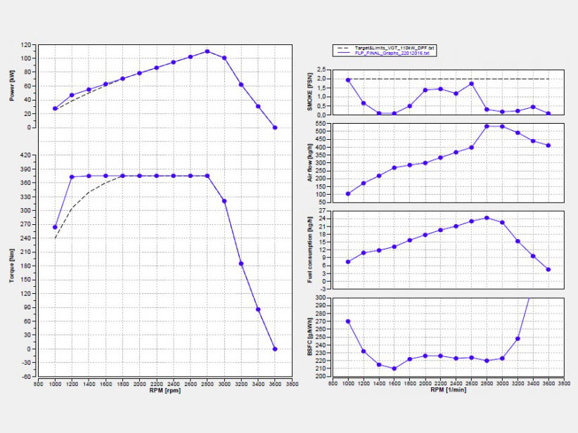
Development tests of engine prototypes conducted on the dyno focus on the selection of individual components and engine systems, their optimization for a given application, verification of technological assumption tests created during the engine design stage on the real object, together with simulation tests. At this stage, engine control unit calibration works are conducted in parallel in order to provide full functionality of engine components.
Functionality tests of engine components and systems are conducted on the dyno in order to verify and assess the operational correctness of individual engine subassemblies. The verification is usually based on the result analysis delivered during durability tests conducted on the testing bench, together with assessments of wear of a given component, subjecting it to meteorological and material tests, as well as via visual inspection.
Test stand 19 enables the examination and testing of Light Duty (LD), Medium Duty (MD) and Heavy Duty (HD) internal combustion engines, as well as electric motors and hybrid propulsion systems.
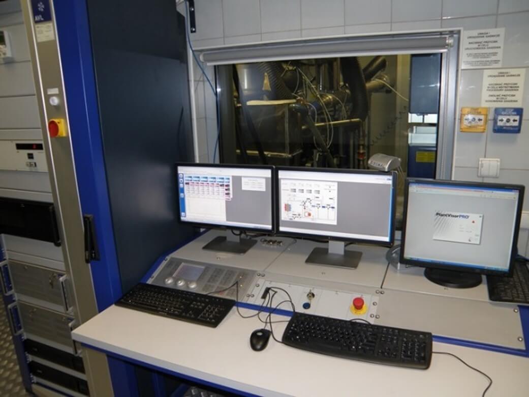
In the second half of 2021. BOSMAL is launching two new dynamic dynamometer test stands with equipment designed for R&D and approval activities for testing and simulating the performance of Heavy Duty (HD) and Light Duty (LD) internal combustion engines fuelled by petrol, diesel, LPG, CNG, synthetic fuels and biofuels with a maximum power output of 560 kW (HD) and 450 kW (LD). In addition, the stand will enable the testing of hybrid propulsion systems with an electric motor output of up to 250 kW. The engines to be tested will operate in steady-state, transient and dynamic conditions.
Parameters of dynamic dynamometers
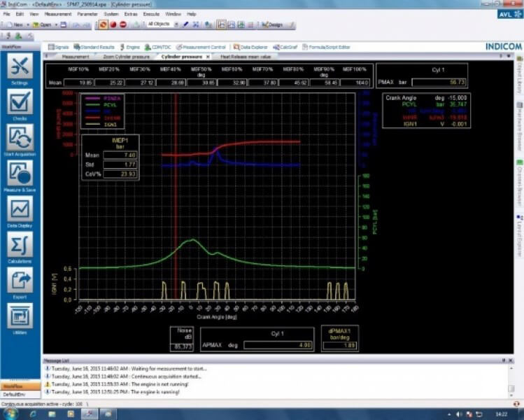
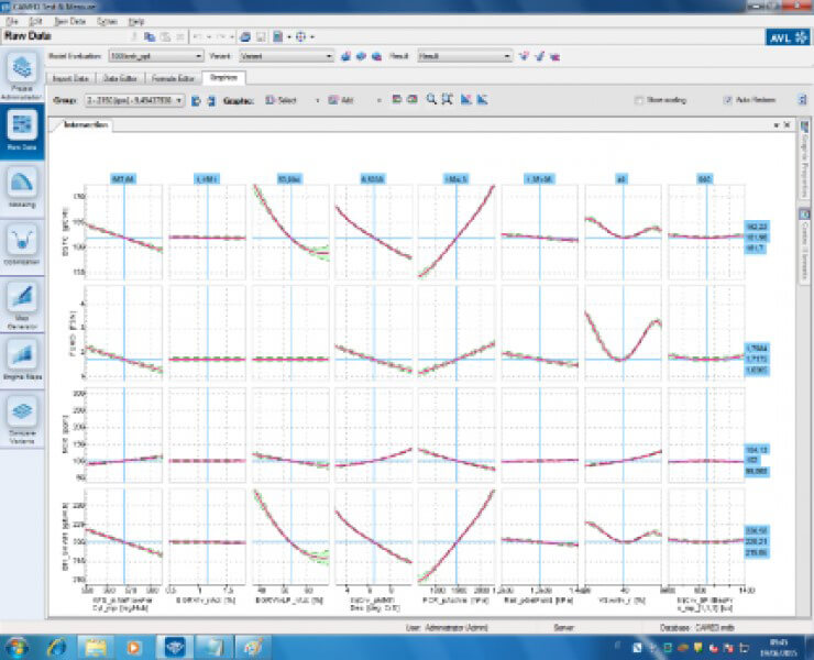
Software
Tests of electric motors, performed on BOSMAL dynamometer benches, covered by Scope of Accreditation AB 128:
Electric motors (maximum power 500 kW) – Measurement of net power and maximum power after 30 minutes on an engine dynamometer – UNECE Regulation No. 85 Series 00
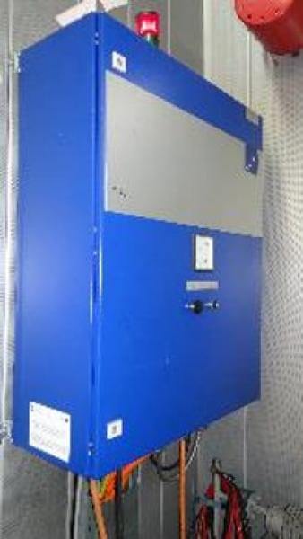
AVL e-storage DC Power Unit
AVL e-storage DC Power Unit
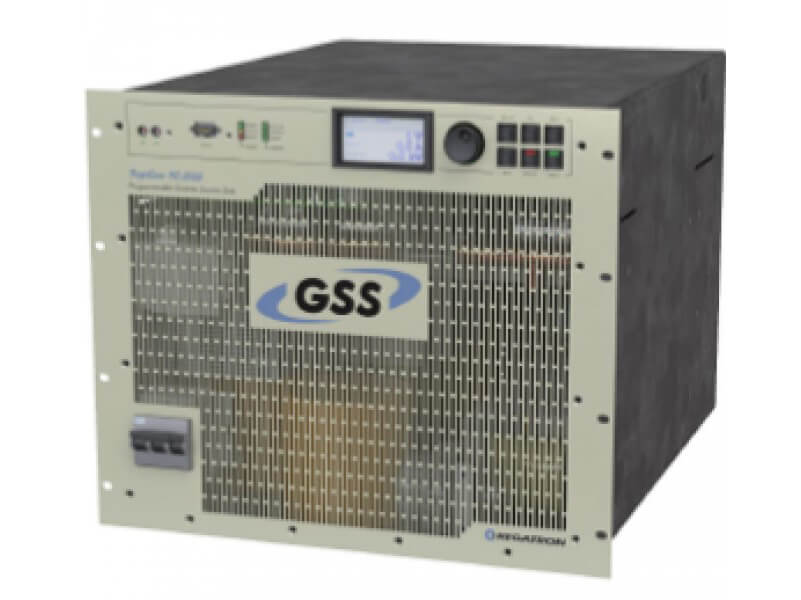
Regatron Low Voltage Battery Emulator
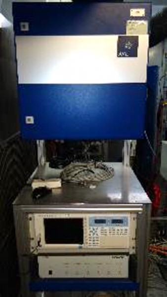
Power Analyzers
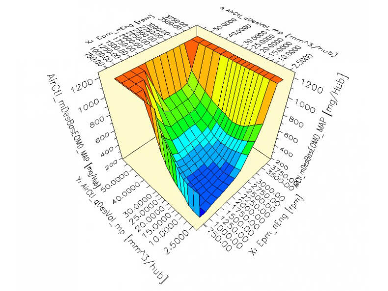
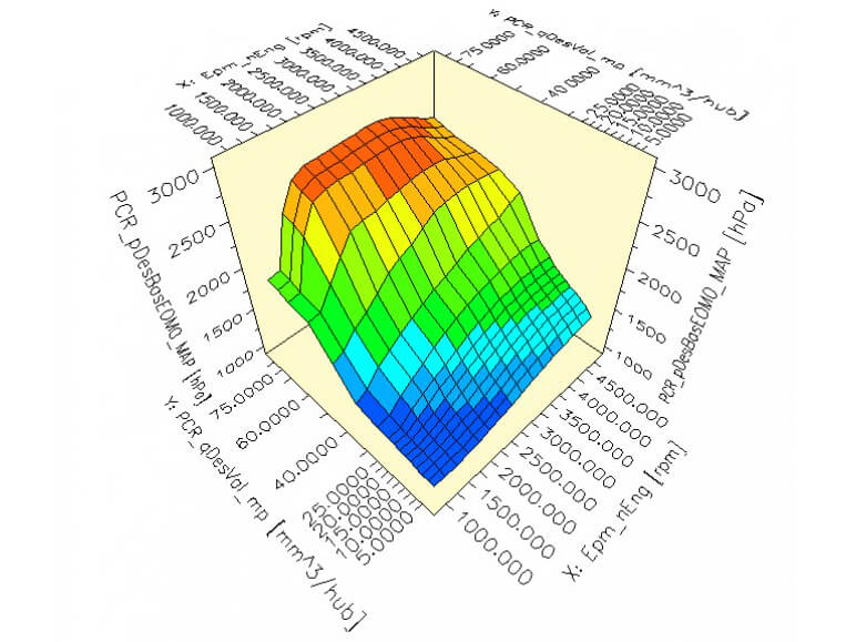
Calibration works carried out on the dyno are performed in order to optimise engine parameters through modification of variables in the engine ECU. Calibration of variables is carried out with the engine working in states determined from partial and maximum load conditions, together with dynamic states, aiming to result in proper engine operation, as well as compliance with technical requirements stated by the manufacturer.
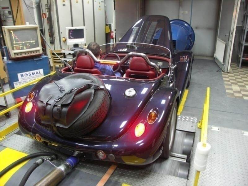
Quality control tests of production engines are conducted on the dyno in order to define the actual engine parameters and compare them with those declared by the manufacturer (e.g. COP – Conformity of Production). During measurements on the engine dyno, parameters such as torque and power at full load, fuel consumption as well as exhaust opacity during free acceleration are measured. These tests gives the ability to identify any anomalies occurring during the engine production process through verification of engine parameters.
Qualification tests of engines and their subassemblies are conducted on the dyno, allowing assessment of the ability to use lower cost subassembly alternatives, without negatively influencing the engine’s durability. ‘Cost reduction’ type of works, which are widely used by manufacturers of engines and individual components, can be an example of such tests, which offer opportunities for economic savings at the production stage.
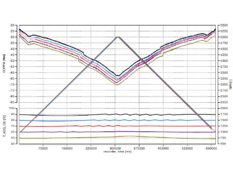
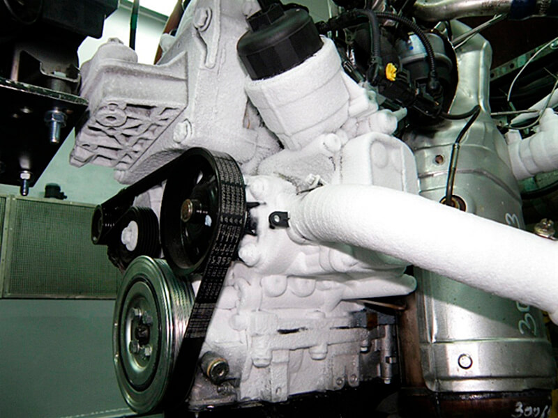
Thermal shock tests are experiments conducted on an engine installed on a dyno, which aim to assess the influence of extreme temperatures of cooling liquid on engine operation, as well as assessing wear and thermal deformation of individual engine components.
During such tests, a glycol cooling medium is used, which is chilled to -35ºC using special apparatus. Next, through heat exchanger systems installed at the test bed, a thermal exchange occurs, which results in the engine cooling fluid reaching -30ºC and being distributed into the engine cooling system. Depending on the test cycle, the engine is heated up to 120ºC, and next its cooling sequence is repeated.
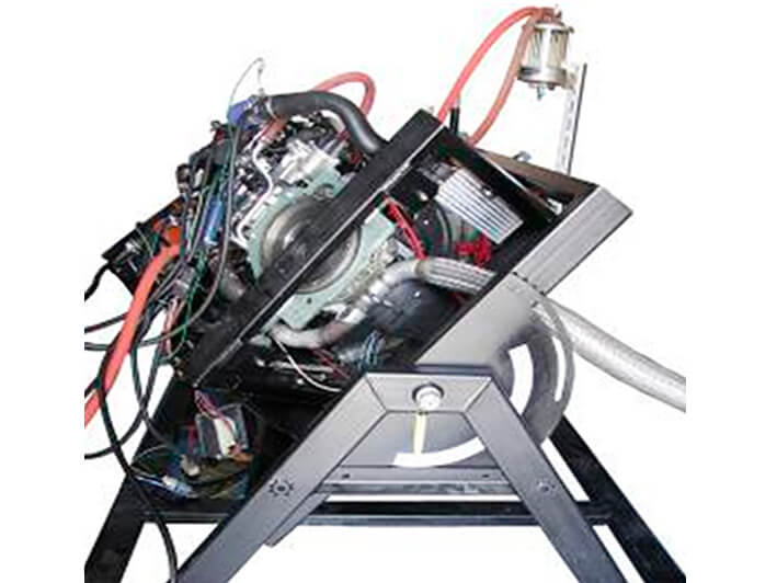
Special tests include non-standard tests performed using specialist test equipment, such as strain gauges to determine material deformation, or tests performed on a specially prepared test stand (TILT), which are designed to determine the specific parameters of the engine and its components.
Validation tests of engines run on the engine dyno aim to determine the durability and reliability of the engine, including its individual components. Such tests, depending on the type of engine (light duty/heavy duty), last from 1000 to 3000 hours and simulate accumulated mileages in the range of 150000 to 500000 km in a relatively short time. At the test bench, any test can be mapped and performed under reproducible laboratory conditions, which facilitates the interpretation of the results obtained and also lowers the test costs in relation to the work carried out on the vehicle. The engines are equipped with a series of sensors that measure the current operating parameters (e.g. temperature, pressure, ECU parameters) registered by the automation system, and at the end of the test, depending on the customer’s requirements, a detailed metrological and material analysis is carried out allowing a final assessment of each component and possible qualification for production.
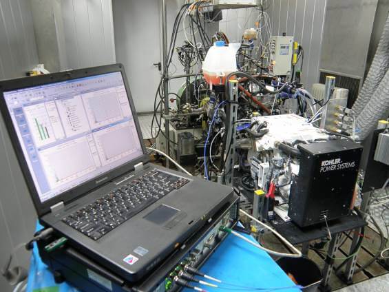
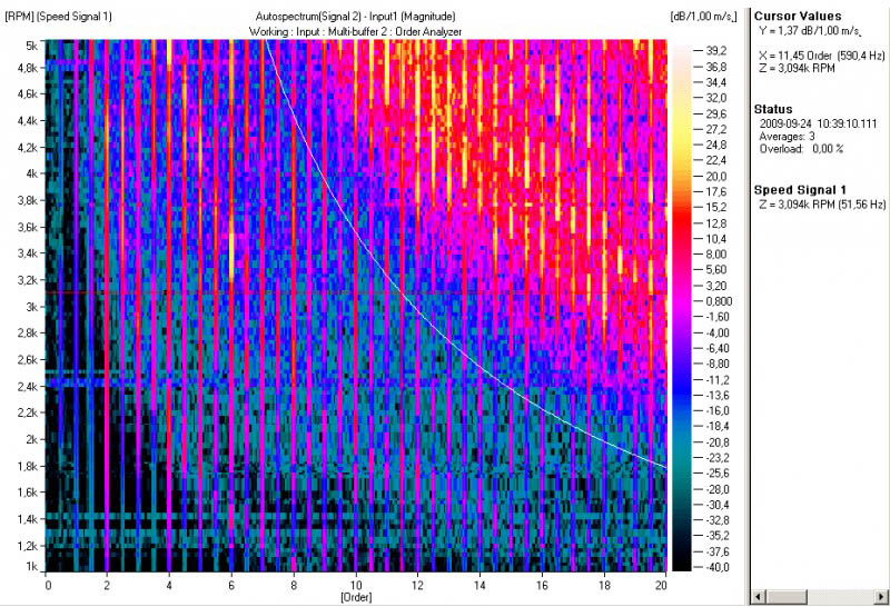
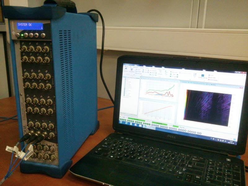
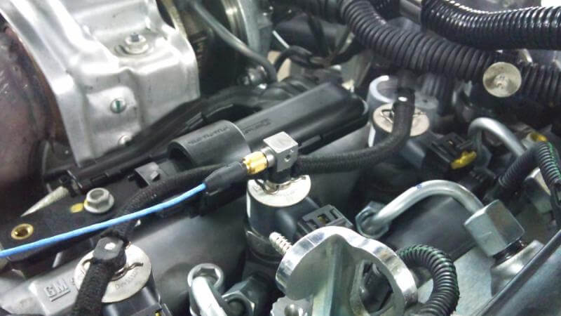
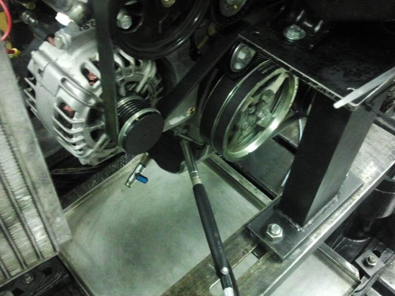
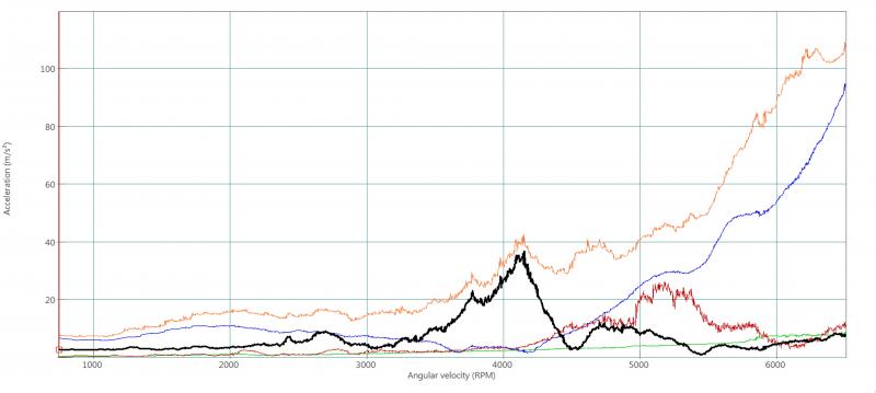
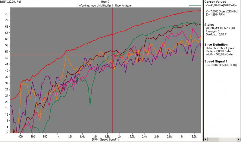
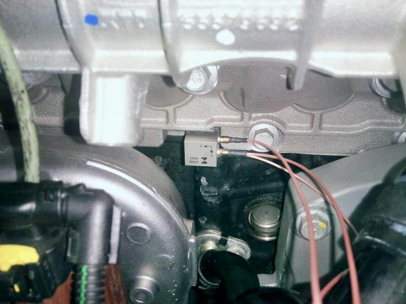
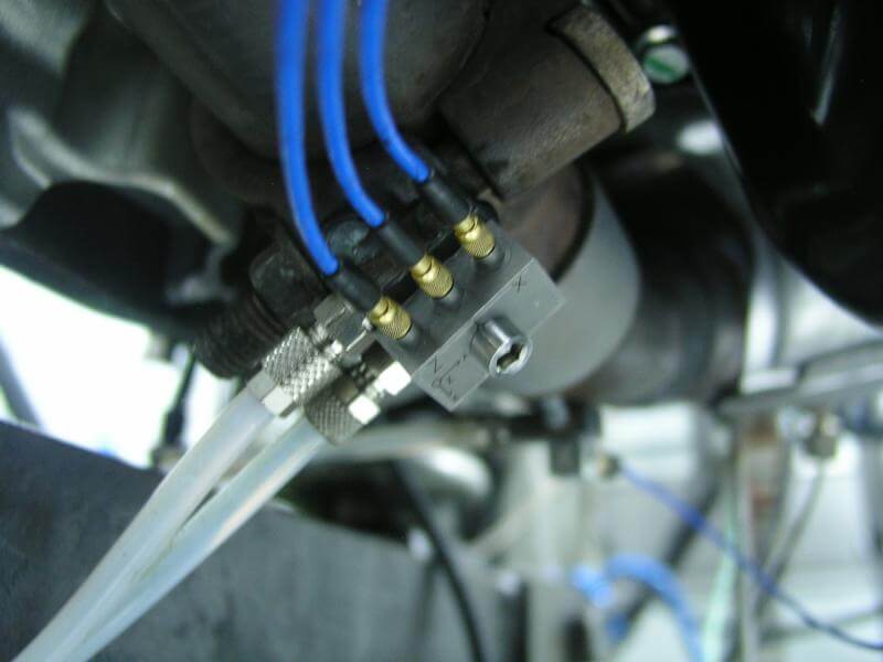
We perform measurements of engine noise and vibrations and the engine dyno. We have performed several dozen such measurements at various locations on the engine: both on the block, sub-systems, turbine and exhaust. We always measure the engine speed at the same time, which is necessary, for example, for Order analysis.
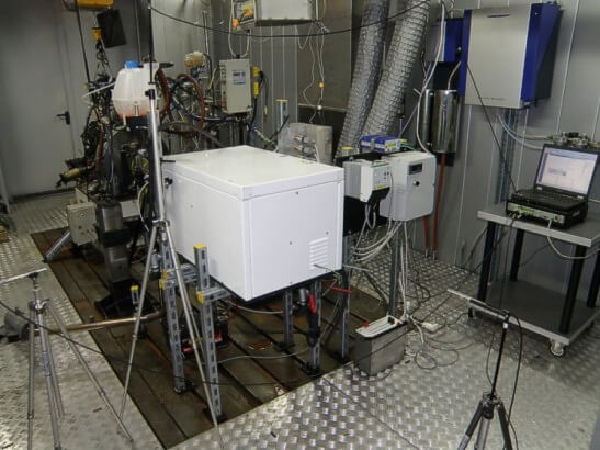
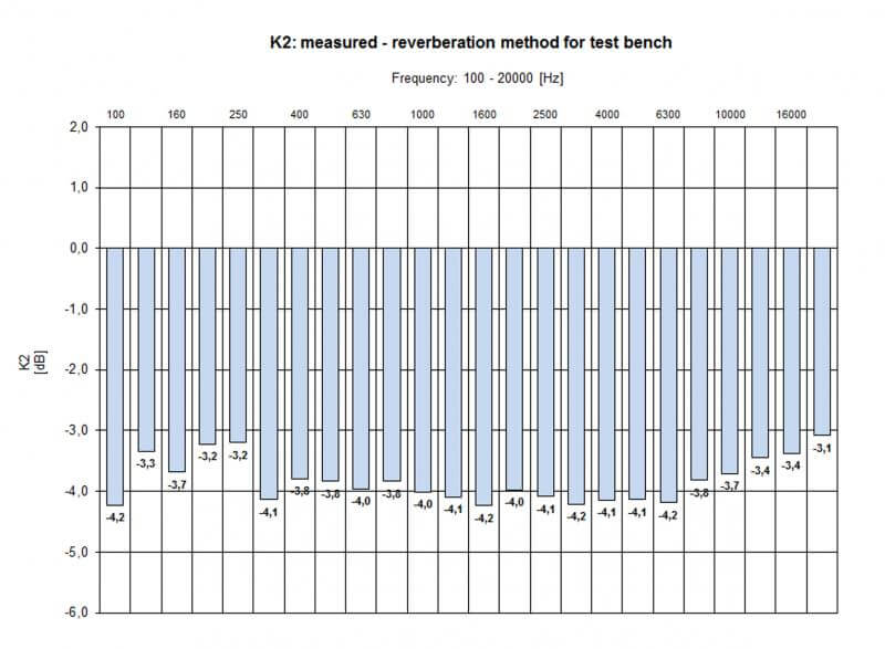
We have assessed the test cells for compliance with the ISO 3746 standard for the determination of sound power by the pressure method. The cells intended for acoustic tests have been adapted accordingly and the K2 correction is sufficiently low.
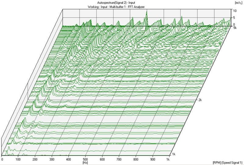
If this is not enough, we can also precisely determine the acoustic power of the engine at constant speeds using an intensity probe.
Measurement results can be elaborated in the form of various graphs, but we can also provide raw data as .uff, .txt, .wav files, and in other formats.